As a follow on to the previous post, this time will cover the hardware and requirements involved in a residential solar system, from panels and inverters, to batteries and wiring.
The Big Picture
The overall goal of any photovoltaic solar system is to turn the radiation from the sun into usable electricity. For the purposes of this we will be subscribing to the particle portion of the wave-particle duality. To begin, an incident photon arrives at our solar panel, constructed of individual photodiodes. The photon is absorbed by a photodiode and creates a current through the photoelectric effect. This current is combined with the many other photodiodes on the panel to the output terminals. Individual solar panels are constructed where they are most efficient, and thus produce the most power, at a particular voltage. As a result, in all but the most minimal of cases a Maximum Power Point Tracker (MPPT) is used. This creates a variable load that is matched to the solar panel outputs, ensuring it operates at the ideal voltage for power production. Next, the current must be converted from direct current (DC) to the common residential alternating current (AC). This is a task for the mighty inverter, which takes the DC current from the MPPT output ranging from tens to hundreds of volts and produces a steady 120V (or even 240V) 60Hz output that can be connected to the residence and grid. Any system with batteries will also need some kind of battery management system (BMS), for older, lead acid type batteries this could be handled by the inverter, but modern multi cell Lithium type batteries require per cell load management to ensure the health and longevity of the battery. Typical items to monitor are cell voltages and temperatures, as well as the current flow to and from individual cells. A BMS also typically reports back State of Charge (SoC) and State of Health (SoH) of the battery back as a whole. Finally, there are numerous methods of wiring these different components together, but most residential applications are subject to some form of the National Electric Code. The Code provides requirements for approved wiring types, safety measures, and all other matter of electrical requirements. Not only does it provide general wiring requirements for houses, but the newest versions have dedicated sections for Energy Storage Systems (ESS) and Photovoltaic (PV) Systems.
Solar Panels
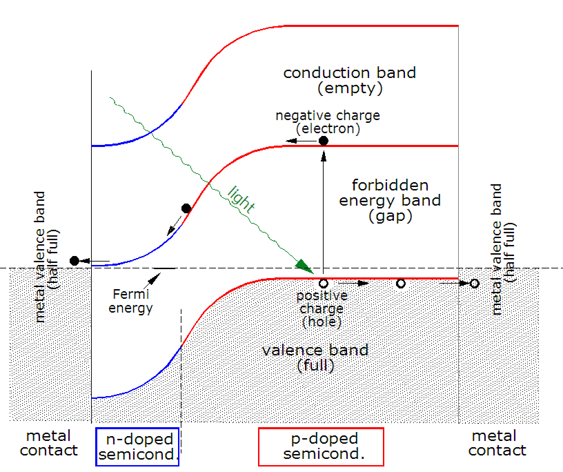
Solar panels are made of solar modules, which are composed individual solar cells that operate with the photovoltaic effect. In the solar cell, a photon strikes the semiconductor material and is absorbed, exciting the electrons in the material to a higher energy state where the electron can move freely in the material. Because the semiconductor material is arranged in such a way to form p-n junctions, current is only allowed to flow in one direction through the cell. Each individual cell in this fashion can only create about 0.5 Volts of potential, so many cells are wired in series to increase the voltage. The exact voltage output is dependent on the individual modules, but most residential and many commercial panels have open circuit voltages, Voc, of less than 600 Volts to remain in the Low Voltage classification of ANSI, as well as the much higher availability of supporting equipment rated to the same levels. In order to increase power more, each collection of series cells can also be put into parallel to provide additional current. Most modern panels also include bypass diodes, which allow current to bypass shaded cells that are not producing power so that the panel can still produce power at a reduced level. Finally, entire panels can also be wired in parallel or series to suit the capabilities of the MPPT and inverter used to capture power from the system, but as in the case with most power generation higher voltages at lower currents results in less loss.
MPPT
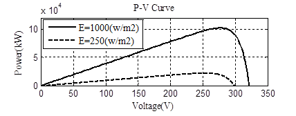
Maximum Power Point Tracking (MPPT) are a critical component of not only photovoltaic systems, but also hydroelectric and wind turbine systems. The core concept is that all of these systems have a nonlinear power-voltage curve, so the output voltage of the generator is controlled via a variable load to stay at the maximal point. A very simple algorithm is the perturb and observe method, where the power output is measured after changing the output voltage. This allows for a hill climbing to the maximum by slowly adjusting the output voltage until the power no longer increases.
Inverters
At the core, modern solid state inverters use MOSFETs to rapidly switch the direction of the DC current flow through a coil, generating an AC current and electric field that can be transformed to a different voltage by the induction of current into a different nearby coil. The quality of the transformation to AC is typically measured via the Total Harmonic Distortion (THD) of the generated signal.
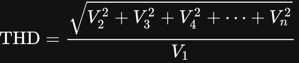
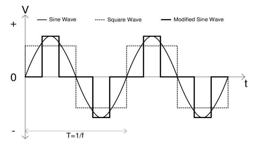
The square root of the sum of the squared voltages of the individual components of the voltage signal is divided by fundamental. Thus, a perfect sine wave will have a THD of 0%, while an ideal delta would have a THD of ∞%. A standard square wave can be easily generated through a H-Bridge MOSFTET configuration but is not without its limitations.4 As known from Fourier decomposition, a square wave is made of an infinite number of decreasing amplitude odd number harmonics, as shown below.
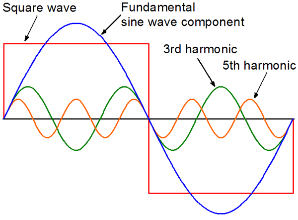
This results in a very distorted signal, which through some clever math can be calculated:

A far cry from the sometimes 3% or less sensitive electronics need. Thankfully, we can play some clever tricks, like a modified sine wave that has multiple discreet steps instead of the binary square wave, as shown below. This smooths out the transitions and results in the higher order components being attenuated, reducing the THD. For the most discerning of applications, significant power filtering is done to attenuate all but the fundamental component.
Batteries
There are several reasons why adding a battery to a solar system makes sense. A fully off grid system with no outside connection needs a power source overnight or during inclement weather when solar yield is low or insufficient if there are no other local power sources available. An unreliable grid or critical infrastructure could benefit for the same reasons. Local utility companies that do not allow net metering or excess production to be sold back to the grid or at a disadvantageous rate provide good reasoning for storing excess power locally as well.
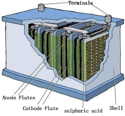
The history of rechargeable batteries is a long one, with the first being a lead-acid type invented in 1859 by Gaston Planté.7 Lead Acid batteries continue to be popular due to their ease of manufacturing and high surge current capabilities, with automotive starting and forklift batteries being prime examples. The main disadvantages of the lead-acid chemistry is the lower energy density compared to other options as well as the generation of hydrogen and oxygen gas during the charging process, leading to potentially hazardous situations.
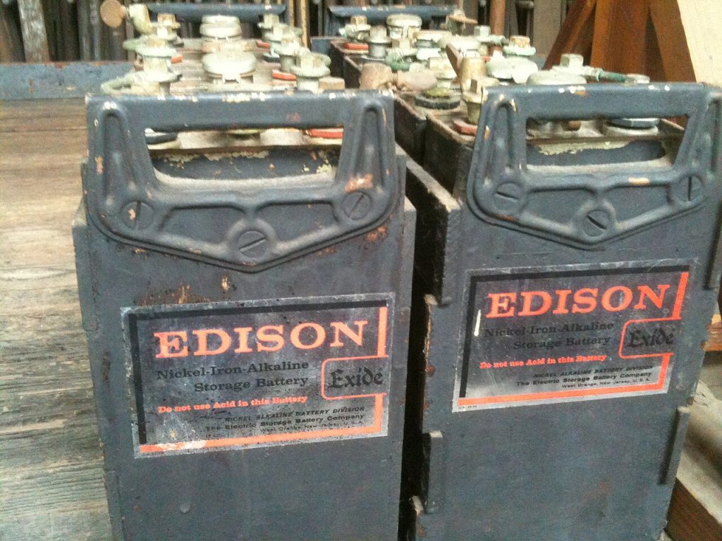
The next major family of rechargeable battery chemistries is that of the nickel type batteries. Waldemar Junger invented the two most common types, the nickel-cadmium and nickel-iron batteries in 1898, the tradeoff between using iron and cadmium being that of cost and performance.9 The cadmium based cells were and continue to be popular due to their availability to deliver their full power over the entire discharge cycle, with the terminal voltage changing very little. Cadmium, however, is one of the more toxic metals in the periodic table, and is being phased out for less dangerous substitutions such as the more recent nickel–metal hydride. Nickel-iron, while less capable than its cadmium brother, was very popular due to its affordability, very long life cycles, and ruggedness. It has more recently been supplanted by lithium-iron batteries, which provide many of the same advantages but do not have the hydrogen gas generation and cell maintenance needs.
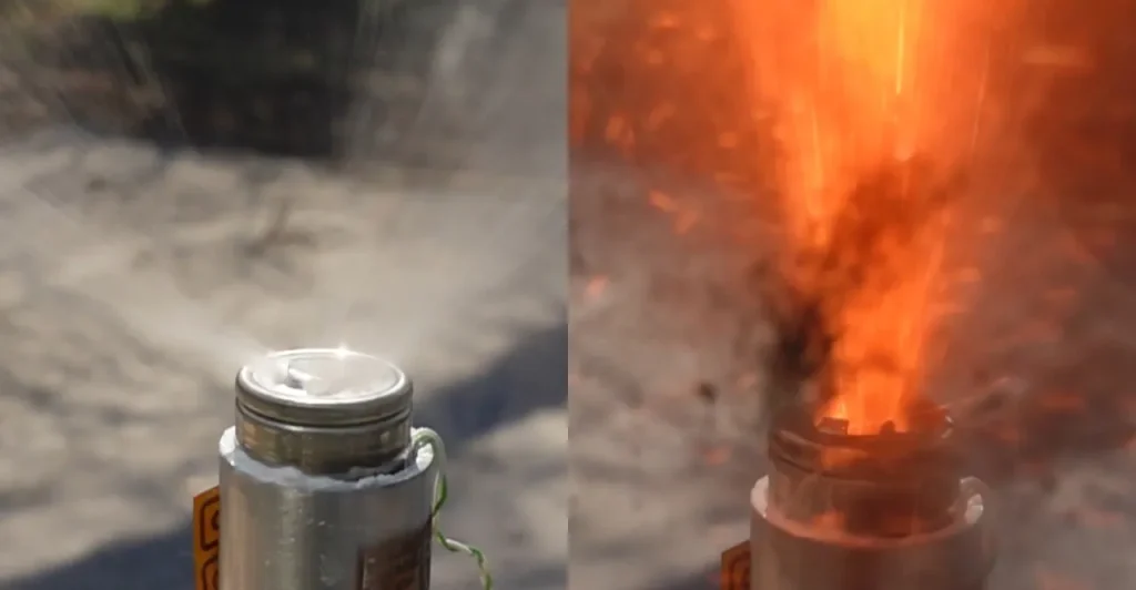
The lithium family has gotten a bad rapport from airlines and safety organizations due to early and poorly manufactured versions over charging and self-destructing due to thermal runaway. During typical operation, the lithium family enjoys very fast charge and discharge rates that do not produce hydrogen gas. The operating temperature ranges of lithium cells are more limited compared to other chemistries, but they also have some of the highest energy densities available. Lithium-iron batteries are a more recent formulation and much like the older nickel-iron chemistry, they are more durable, less sensitive, and safer batteries at the cost of some performance.
Wire and Conduit
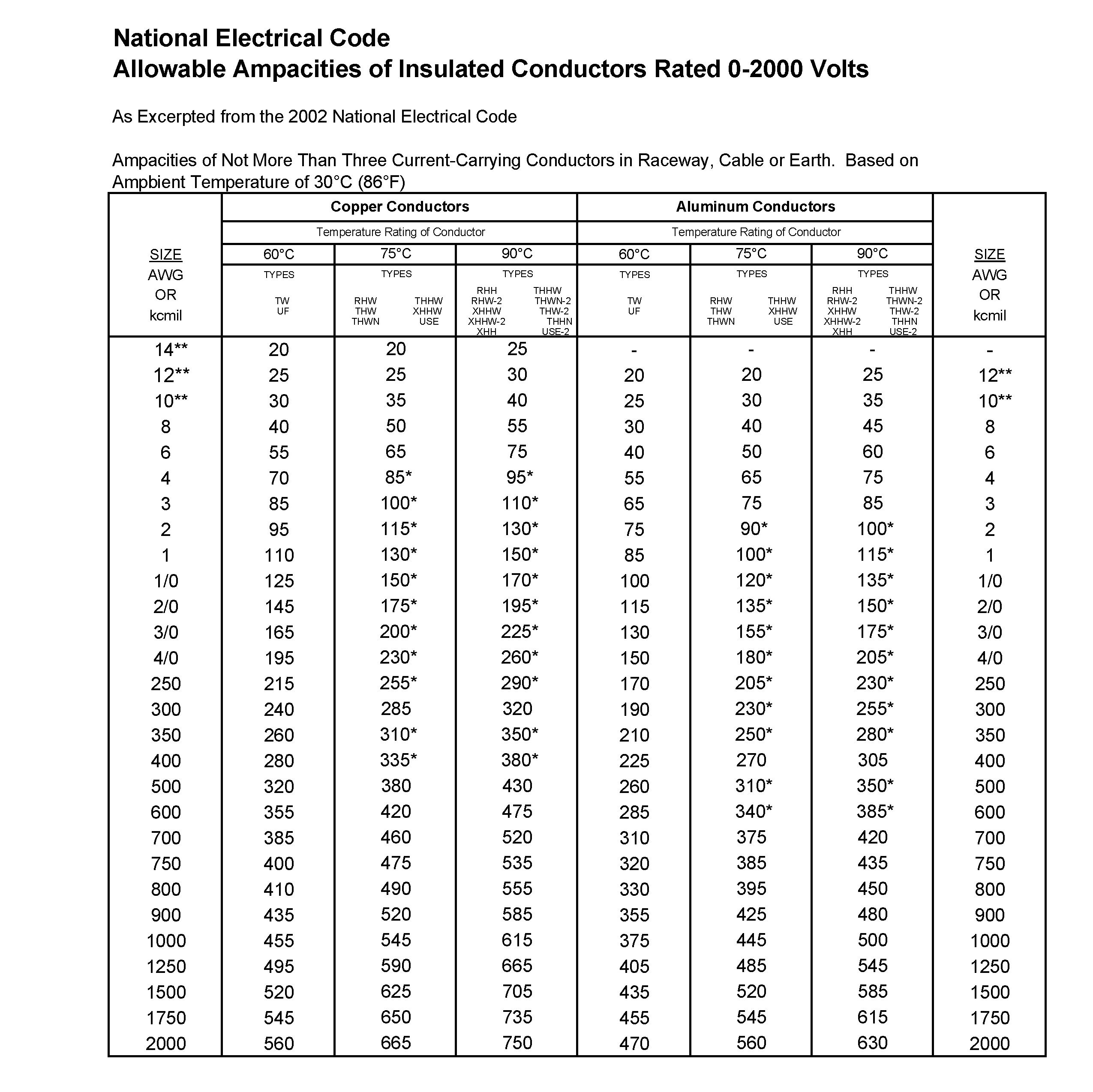
The National Electric Code provides the most boundaries for residential use in the United States, and also provides an ampacity table for conductor size, material, temperature rating, and derating to account for high temperatures and number of conductors collocated. In practice, #10 AWG copper is the standard for connecting solar strings due to its high availability, ampacity, and lower voltage drops. Smaller systems that do not generate as much current can use #12 or #14, however they will experience higher voltage drops and power loss. Larger systems or those with very long feedlines that cannot be shortened may need to increase to #8 or larger to avoid such power loss. For larger feeder wires from the inverter AC output aluminum service entry cable is a good choice that is readily available in 100 to 200 Ampere rated flavors. Although aluminum must be two sizes larger than copper for the same ampacity, for such large loads copper is prohibitively expensive, especially over long runs. Battery cables can be undersized for their current output if they are using short jumpers to connect to larger bus bars that are rated appropriately. Due to the very high currents and relatively low voltages out of battery systems, they should be placed as close to the inverter as possible with as low loss cable that is affordable to avoid power loss with large bus bars and conductors used where possible.
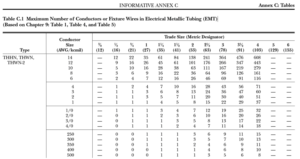
Conduit, that is the container for the wiring, is also regulated by the National Electric Code. There are some special restrictions noted in the code, such as all Direct Current conductors that are on the interior of a residential structure need to be in a metallic conduit such as Electrical Metallic Tubing (EMT) or Flexible Metal Conduit (FMC). Conduit should also be labeled appropriately to indicate that it is a photovoltaic conductor. There are also limits on how many conductors of a particular size can be ran inside conduit of a certain size. Naturally, there is convenient tables to quickly reference common options, along with formulas for more complicated situations. It is important to note that some cable types such as Non Metallic (NM) and Service Entrance cable (SER) are rated for and typically installed not in conduit unless needed for physical protection due to their size and installation difficulty compared to cable such as THHN. Beyond code requirements, the type of conduit used is a matter of installation requirements such as moisture levels, above or below ground installations, installation space available, and proximity to damage. Non metallic options such as PVC, Electrical Nonmetallic Tubing (ENT), and Liquid-Tight Flexible Conduit (LFNC) are typically the easiest to install due to ease of cutting and assembly. Metallic options such as EMT, FMC, and Liquid-Tight Flexible Metallic Conduit (LFMC) provide higher protection levels but can be more difficult to work with and install.
Sources
- Physics:Theory of solar cells – HandWiki ↩︎
- File:Power-voltage (P -V) curve.png – Wikimedia Commons ↩︎
- Total Harmonic Distortion ↩︎
- H-bridge – Wikipedia ↩︎
- File:Squarewave01CJC.png – Wikimedia Commons ↩︎
- DOI:10.24003/emitter.v9i1.587 ↩︎
- https://www.corrosion-doctors.org/Biographies/PlantelBio.htm ↩︎
- https://www.researchgate.net/publication/266345609_Accurate_circuit_model_for_predicting_the_performance_of_lead-acid_AGM_batteries ↩︎
- https://en.wikipedia.org/wiki/Waldemar_Jungner ↩︎
- https://commons.wikimedia.org/wiki/File:Thomas_Edison%27s_nickel%E2%80%93iron_batteries.jpg ↩︎
- Sensor May Prevent EV Thermal Runaway ↩︎
- https://usawire-cable.com/wp-content/uploads/nec-ampacities.pdf ↩︎
- https://www.electricallicenserenewal.com/Electrical-Continuing-Education-Courses/NEC-Content.php?sectionID=553 ↩︎
_curve.png)
Leave a Reply